Drive-Drive Power is a new way to build the heart of an electro-hydraulic system: the pump. In a conventional electric pump, a single motor turns a single drive gear while a second gear simply follows along as an idler — present to seal the pumping chambers, but contributing no power. Drive-Drive replaces that idler with a second, fully powered motor. Now both gears drive — two independent power inputs feeding one shared hydraulic output, cascading into advantages in capability, reliability, efficiency, and thermal behaviour that a single-motor pump cannot match.
The core idea
Both gears powered, kept in step by software.
Inside one pump housing sit two meshing gears. In the conventional
Simplex
(single-drive) arrangement, one motor powers Gear A; Gear B is a passive idler. In the
Drive-Drive
arrangement, a dedicated servo motor powers each gear — Gear A and Gear B are both power-input gears.
The two motors are never connected by a shaft, a belt, or any mechanical link. Their only physical connection is the gear mesh and the oil they jointly pressurise. They are kept in step electronically: each servo drive runs the same motion command, and the two stay synchronised by software, not by hardware.
The Drive-Drive distinction in one line
One change, everything cascades.
Simplex
— one motor drives, one gear idles.
Drive-Drive
— two motors, both gears drive, synchronised electronically, coupled only through the oil.
The two architectures
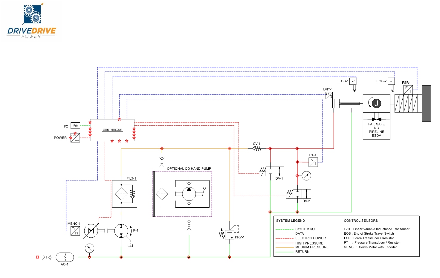
Identical hydraulics — only the drive changes.
Side-by-side, the only difference between a conventional electro-hydraulic actuator and the Drive-Drive is the pump itself: one powered gear versus two. Same valve, same hydraulics, same safety logic.
Drive-Drive SystemDrive-Driven System
What "two powered gears" actually buys you
Twice the force budget — the right trade for heavy duty.
Because both motors push on the same fluid, their torques add. A Drive-Drive pump built from two motors has twice the torque budget of a single motor of the same size — and torque, in a pump, is pressure. What does not double is the top speed: the two gears are locked together by their mesh, so the pump can never spin faster than one motor's rated speed. That is exactly the right trade for heavy-duty actuation, where the hard demands are high force and high pressure, not high speed.
Capability
Single motor (Simplex)
Two motors (Drive-Drive)
Torque / pressure budget
1×
2× (the motors' torques add)
Speed ceiling
1×
1× (shared gear mesh)
Flow at a given speed
Full
Full
Power inputs to the pump
One
Two, independent
Built-in redundancy — the headline benefit
A single failure means continue, not stop.
The two-powered-gear architecture is inherently fault-tolerant. If one motor fails for any reason — a winding fault, a drive trip, a lost encoder, a tripped breaker, even a severed cable — the surviving motor keeps turning its gear, and the failed motor's gear is simply carried along by the mesh as a temporary idler. The failed motor can be electronically isolated in milliseconds by zeroing its torque command, so a fault on one channel cannot disturb the other.
Drive-Drive
Graceful degradation
One motor down means the system continues at a reduced force budget rather than stopping. Because the two motors can be fed from independent drives, cables, and even separate electrical supplies, the architecture rides through a single failure anywhere in the entire power chain.
Simplex
Total loss of output
A conventional single-motor pump has no such fallback: the same fault stops the pump completely. There is no survivor to carry the load and no way to ride through — the valve is stuck wherever it happened to be.
Graceful degradation, not failure
One motor down on a Drive-Drive pump =
100% of flow capability retained
, force budget halved, full electronic control kept on the survivor.
The same fault on a single-motor pump =
total loss of pump output
.
A quieter, cooler, more efficient pump
Drive both gears, and most of the mesh-friction loss disappears.
In a single-drive pump, the idler gear has to receive its share of the pumping torque through the gear teeth, loading the mesh with a large contact force that wastes energy as friction and heat. In a Drive-Drive pump each gear is driven directly, so the mesh carries only a light sealing load. Most of that mesh-friction loss disappears — heat that never has to be carried away by the oil.
The architecture also unlocks control freedoms a single motor cannot offer. The two motors can deliberately share the load unequally — biasing work toward the cooler of the two, or away from one showing early signs of wear — all in firmware, with no effect on the pump's output. And because two independent torque signals act on one shared shaft, the difference between them is a continuous, built-in health signal: a free diagnostic that a single-motor pump simply does not have.
Where it fits
A drop-in concept for electro-hydraulic actuation.
Drive-Drive Power is a drop-in concept for electro-hydraulic and electro-hydrostatic actuation across oil & gas, industrial, and heavy-equipment applications — anywhere a hydraulic actuator must be powerful, dependable, and increasingly electric. It is especially compelling for safety- and availability-critical duties such as emergency shutdown valves, where an unexpected stop is expensive — and, with a section blocked in, potentially hazardous — and a guaranteed fallback is worth a great deal. The rest of this page shows exactly how the technology performs in that setting — measured, not asserted, through a full engineering digital twin.
Why Drive-Drive
Both designs meet the spec. Only one keeps running when something fails — and costs less to own.
The eight differences that matter
The real differences appear around the specification.
When a component fails, when the motors heat up, when a proof test is due, and when the accountant totals up 25 years of ownership — on every one of those axes, Drive-Drive wins. All of it measured on the digital twin.
1
Guaranteed redundancy
Either motor alone can open the valve under the worst conditions in the test suite — inside its continuous rating, not by overloading. The surviving motor runs with about a
1.9× margin
, the same comfortable margin the Simplex baseline is designed to. A guarantee backed by a hard test checkpoint.
2
No "stuck halfway" failure
On a single-motor system, a mid-stroke motor failure leaves the valve stranded part-open — and a valve that cannot complete its stroke is a safety issue, not merely a process upset. A blocked-in section that cannot be relieved builds pressure toward rupture; under fire, trapped inventory escalates toward a BLEVE; on fail-open flare and vent duty, failure to open can send toxic or flammable gas into occupied areas. On Drive-Drive the same failure is a non-event: the survivor picks up the load instantly and the stroke completes normally.
3
Safer, smarter proof testing
Regulations require ESDVs to be partially stroked periodically. On a single-motor system, a motor that fails during the proof test can drag the valve into an unwanted full closure. On Drive-Drive the proof test completes on one motor — and an operator can intentionally test on a single motor to prove the redundancy is healthy, without risk to the valve.
4
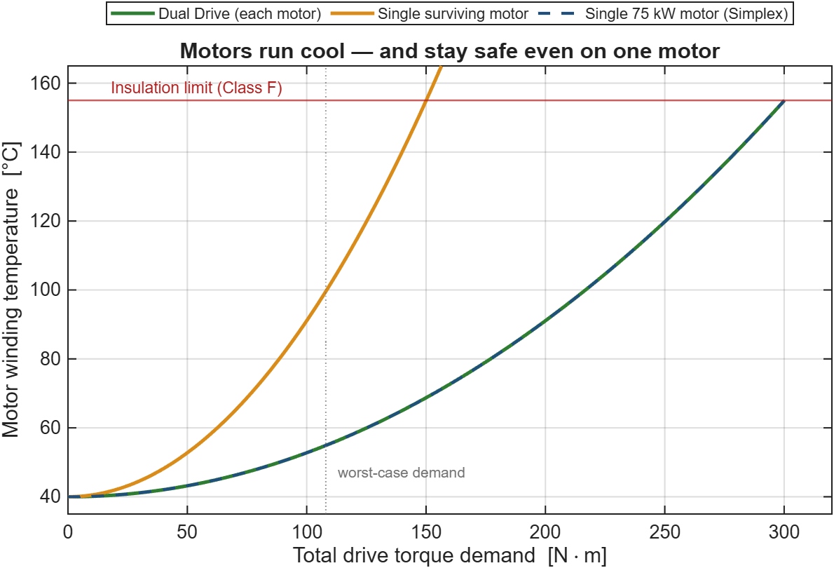
Cooler, with thermal margin to spare
Splitting the work across two motors quarters each one's resistive loss. At the same total load, each Drive-Drive motor produces about
two-thirds less heat
than the single large motor, and the pair together about a third less. Even a lone survivor carrying the entire worst-case load settles well below its insulation limit.
5
A more efficient pump
Driving both gears removes most of the gear-mesh friction loss of a single-drive pump. The twin's physics-based model puts the mechanical-efficiency gain at roughly
two and a half points
— energy that never becomes waste heat in the oil, which matters most in a sealed circuit where the fluid is also the heat sink.
6
A pump that monitors its own health
With two independently measured motor torques acting on one shaft, the difference between them is a live, sensor-free window into the pump's internal condition. A drift flags rising friction, bearing drag, or gear wear during normal operation, with no added instrumentation. A single-motor pump has nothing to compare against.
7
An order-of-magnitude reliability gain
A Drive-Drive system loses the valve only if both channels are down at once — the product of the two probabilities, plus a small common-cause term. For realistic numbers this is a
ten- to twenty-fold reduction
in drive-related unavailability, and the surviving half runs at full performance rather than limping.
8
Smaller motors, smarter spares
Two motors that together match one larger motor are each physically smaller — roughly
a quarter smaller per frame
than the single unit they replace — and cheaper per unit. One spare covers either position, so a site stocks half the spare capacity. A failed motor is swapped at the next convenient window, valve still in service.
A motor fails 10 seconds into opening. The surviving motor instantly takes the full load, and the valve finishes on time. The valve cannot tell that half the drive just vanished.
Steady motor temperature versus load. Each Drive-Drive motor runs cooler than the Simplex motor at every load. Even a lone surviving motor stays under the insulation limit across the whole operating range — so single-motor operation needs no temperature restriction.
Safety
When a valve fails to open, it is not just downtime.
On a fail-close ESDV, the spring guarantees closure — that half of the safety duty is untouchable. The other half depends on the drive: opening the valve, completing a stroke, restoring a relief or flow path on demand. On a single-motor system, one motor or drive failure removes powered actuation entirely — and what follows is a hazard chain, not an inconvenience.
1
Overpressure & equipment rupture
If an emergency depressurisation (blowdown) valve fails to open, pressure inside the pipeline or vessel builds to unsafe levels. With no safe escape route, the equipment can rupture — triggering explosions.
2
Escalation under fire — BLEVE
A blocked-in section that catches fire undergoes violent thermal expansion. If the relief or blowdown path fails to open, the trapped gas and liquid expand until the vessel explodes — the industry's BLEVE scenario (consequence analysis).
3
System choke & backflow
In compressor stations and processing trains, a valve that will not open blocks necessary relief paths. Explosive fluids can be forced back into low-pressure systems, and upstream machinery can fail catastrophically.
4
Loss of venting control
Flare and vent ESDVs are designed to fail open — diverting toxic, sour (H₂S-rich), or flammable gas safely away from personnel. A failure to open can vent dangerous gas clouds directly into occupied work areas.
How Drive-Drive mitigates these risks
Every one of these hazard chains begins the same way: a single motor or drive failure that removes powered actuation. Drive-Drive removes that single point of failure. Either motor alone completes the stroke inside its continuous rating — with a 1.9× thermal margin — so the valve still opens, the stroke still completes, and the relief or venting path is restored on demand.
The continuous cross-motor health signal adds a second layer: developing degradation is flagged during normal operation, before a demand ever finds a weakened drive. The certified fail-close function is untouched throughout — the spring closes the valve either way — so the mitigation is pure gain: the failure-to-open hazard chains above are cut at their first link. Performance figures are model-derived on the digital twin, pending experimental validation.
Total cost of ownership
The one number a buyer cares about: lifetime cost of ownership.
We built a bottom-up total-cost-of-ownership model for the actuation package with two independent field experts — an OEM/distributor and a pipeline operator. Over the field life, the Standard (simplex) package totals $864,505 against $645,575 for Drive-Drive — a saving of $218,930 (25.3%). Drive-Drive does cost more to buy — about $47,500 more in acquisition — but that premium is repaid over the service life through lower maintenance and, decisively, zero production-halt exposure: a single motor failure no longer stops the valve. The same failure mode is also a genuine safety exposure — a valve that cannot open or complete its stroke can leave a section blocked in with no relief path — so eliminating it buys both economics and risk reduction; the cost model below conservatively counts only the economics. The model’s expected actuation-failure count over the life is 0.10, matching independent FMEDA reliability data (OREDA / exida).
Cost component (actuation package · field life · undiscounted USD)
Standard (simplex)
Drive-Drive (dual-drive)
A · Acquisition & installation (one-time)
$332,500
$380,000 (+$47,500)
B · Maintenance (annual × field life)
$388,108
$265,575 (−$122,533)
C · Failure & downtime (lifetime)
$143,897
$0 (rides through)
Total cost of ownership
$864,505
$645,575
Saving with Drive-Drive
—
≈ $218,930 (25.3%)
Expected actuation failures over life
0.10
0 (redundant)
The conclusion is robust. The biggest single driver is the value of lost production — modelled here at $300,968/day, the mid-point between a bottom-up pipeline-tariff estimate and direct operator input, and conservative against published O&G downtime benchmarks of about $496,000 per hour (Siemens, The True Cost of Downtime 2023). Because the failure-and-downtime exposure falls entirely on the single-motor system, any reasonable downtime value leaves Drive-Drive ahead. Field life is 12.5 years for the Standard system and 15 years for Drive-Drive, reflecting its longer expected service life.
How we got these numbers
In plain English — how we got these numbers.
This section explains, step by step and without any maths, where each headline number comes from. It is written so that anyone — not just an engineer — can follow the logic. The same five-step method produces all three duties above; the final step shows what changes between them.
Step 1 — What it costs to buy ($332.5k vs $380.0k). We added up the equipment (motor, hydraulic power unit/pump, controls — excluding the valve body itself) plus installation and commissioning. Drive-Drive comes out about $47.5k more expensive to buy, because a dual-drive package carries a second motor channel. This is the one place the Standard system is cheaper.
Step 2 — The yearly maintenance ($31.0k/yr vs $17.7k/yr). Working with the field experts, we costed every recurring task on its real interval: partial-stroke tests, full proof tests, visual/external inspection, hydraulic-fluid analysis, HPU preventive maintenance, SCADA/comms checks, and periodic major overhaul. Drive-Drive runs materially cheaper per year because its diagnostics are remote/condition-based — the same SIL-mandated tests cost less to perform and resolve right first time. Over the field life that is $388.1k for Standard vs $265.6k for Drive-Drive.
Step 3 — The decisive one: failure & downtime ($143.9k for Standard, $0 for Drive-Drive). Over the 12.5-year life the expected number of dangerous actuation failures is about 0.10 — a figure that matches independent reliability data (OREDA / exida FMEDA). For the single-motor Standard system, such a failure can halt production. We cost that as: expected failures (0.10) × share that halt production (100%) × outage length (4.75 days) × value of lost production ($300,968/day), plus the repair cost — about $143.9k over the life. For Drive-Drive this is zero: if one motor fails, the second keeps the valve working, so no production is lost. That single difference drives the result.
Step 4 — The value of lost production ($300,968/day). This is the largest swing factor, so we did not guess it. It is the mid-point of a bottom-up pipeline estimate (barrels blocked × transportation tariff × the unrecovered share of revenue) and a direct operator input — and it sits well below published O&G downtime benchmarks of about $496,000 per hour. In other words, the figure we used is deliberately conservative.
Step 5 — The totals ($864.5k vs $645.6k). Acquisition plus field-life maintenance plus failure-and-downtime gives $864,505 for the Standard system and $645,575 for Drive-Drive — a saving of $218,930 (25.3%). The gap comes from Drive-Drive’s lower maintenance and its elimination of the production-halt exposure that only the single-motor system carries. That is the midstream case, shown in the first chart above.
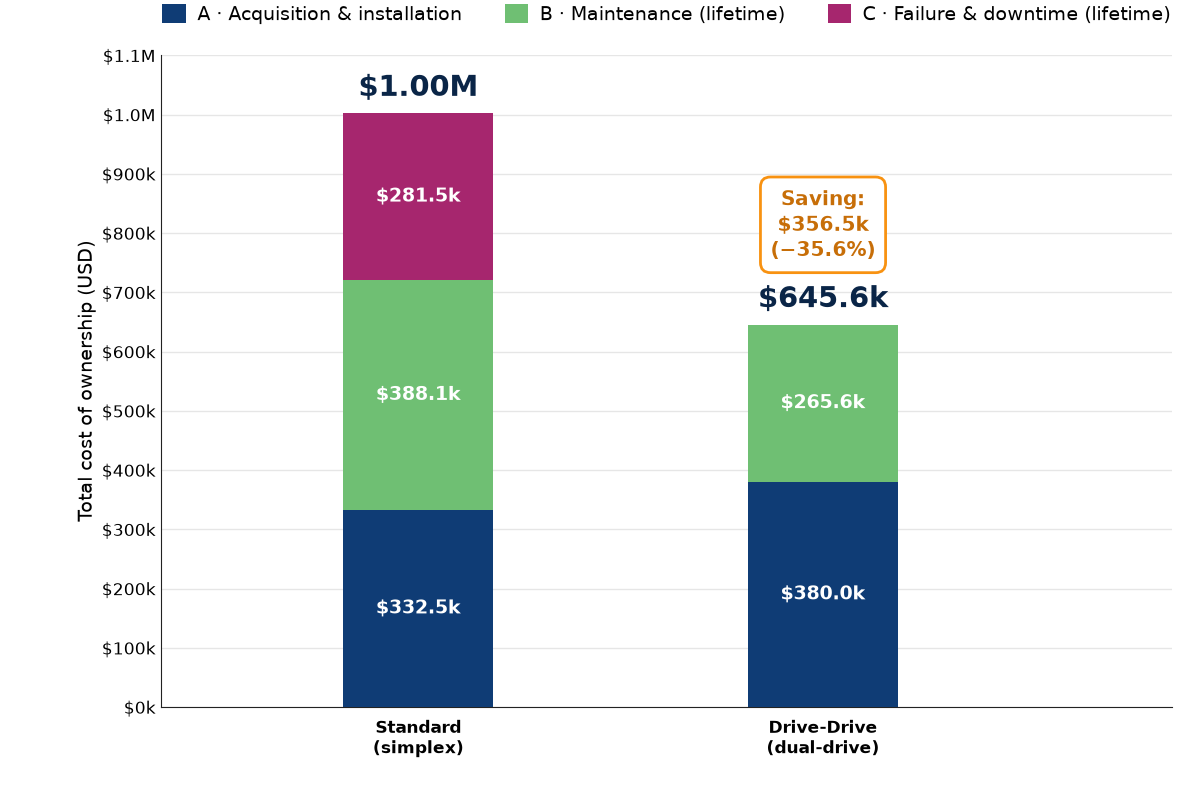
Step 6 — The same method, three duties (25.3% → 35.6% → 49.4%). The two upstream charts use this identical A/B/C method — only the inputs change to match each application. Upstream onshore uses the same valve as midstream, so acquisition and maintenance are unchanged and the Drive-Drive total is identical ($645.6k). The one thing that changes is the value of what stops flowing: a producer loses oil at its netback (~$50/barrel) rather than a pipeline tariff (~$6.27/barrel), so a single-motor failure now carries $281.5k of downtime exposure instead of $143.9k — lifting the Standard total to $1.00M and the saving to 35.6%. Upstream offshore is a SIL 3 duty: the valve itself costs more (more redundancy, diagnostics and qualification), offshore maintenance and repairs are dearer, and an outage lasts far longer (14 days) at a higher production value. Every component grows, so the Standard total reaches $2.50M against $1.27M for Drive-Drive — the largest saving of all at 49.4%. The pattern is consistent: the more a stoppage costs, the more the redundant design saves.
Midstream (SIL 2). Standard \$864.5k vs Drive-Drive \$645.6k — saving \$218.9k (25.3%). Lost production valued at the pipeline transport tariff.Upstream onshore (SIL 2). Standard \$1.00M vs Drive-Drive \$645.6k — saving \$356.5k (35.6%). Same valve as midstream; lost production valued at oil netback.Upstream offshore (SIL 3). Standard \$2.50M vs Drive-Drive \$1.27M — saving \$1.24M (49.4%). Higher-cost SIL 3 valve, longer offshore outages — the largest saving of all.
Actuation-package total cost of ownership over the field life (undiscounted), from the field-expert bottom-up model, shown for all three duties. Each chart uses the identical A/B/C method; the scales differ because offshore totals are far larger. Drive-Drive is the lower-cost choice in every duty, and its advantage widens as the value of lost production rises.
Every driving number is anchored to a published source below.
Model basis & sources. Field-expert bottom-up model (Field Expert (OEM & distributor)), field life 12.5 years (Standard) / 15 years (Drive-Drive). Value of lost production $300,968/day — mid-point of a bottom-up tariff estimate and operator input, conservative against published O&G downtime of ~$496k/hour (Siemens, 2023). Transportation tariff $6.2742/bbl per the Dakota Access FERC committed rate. Expected-failure rate cross-checked against OREDA / ISO 14224 and exida FMEDA component data. All model formulas independently reconciled.
What Drive-Drive does not claim
Credibility means being clear about the limits too.
It is not faster
Opening speed is set by pump flow, which is the same in both. Drive-Drive opens the valve in the same time, not less.
No meaningful energy saving
An ESDV strokes only a few dozen times a year; the efficiency and heat gains are real engineering benefits, not an energy-bill story.
It is not safer
The spring owns the safety function in both systems. This is also a feature: the upgrade needs no safety re-certification.
It costs more to buy
The value is in ownership and availability, not purchase price. Drive-Drive carries roughly a 28% drive-train premium up front.
The bottom line
Both designs pass every test. Only one keeps the valve working when something breaks.
A single-motor actuator meets the specification. A Drive-Drive actuator meets the same specification with two smaller, cooler motors — and turns every single-point electrical failure from a production-stopping emergency into a routine, planned repair.
It is more available, runs cooler, monitors its own health, and over the field life costs roughly
$218,900 (25%) less to own
— all without changing the certified safety case. Only one design pays you back for the privilege.
Want a technical briefing?
Walk through the digital twin, the 18-checkpoint test suite, and the full cost model with our engineering team.